


Sauna Ventilation for Designers: Quantitative CO2, PM2.5, and Air Change Targets for Small Residential Rooms
For small residential saunas, design ventilation around three measurable targets: keep occupied CO₂ below roughly 1,000–1,200 ppm, use 15 µg/m³ PM2.5 as a conservative short-term planning reference (especially for wood-fired systems), and size for approximately 5–10 air changes per hour (ACH)—then verify every target with instruments after installation.
TL;DR
-
CO₂ target: Keep occupied sauna CO₂ below ~1,000–1,200 ppm; rising CO₂ signals inadequate fresh-air delivery for the occupant load. [EPA; ASHRAE 62.1]
-
PM2.5 target: Use the WHO 24-hour guideline of 15 µg/m³ as a conservative planning reference; wood-fired systems demand closer attention here. [WHO 2021]
-
ACH range: Plan for 5–10 ACH in small residential saunas—this range is industry-informed and extrapolated from IAQ principles, not a universal code requirement. [North American Sauna Society; LocalMile; ASHRAE extrapolation]
-
CFM formula: Room volume (cu ft) × target ACH ÷ 60 = required CFM.
-
Airflow path matters as much as flow rate: Short-circuited vents can meet ACH targets on paper while failing to dilute CO₂ at occupant level.
-
Commission with instruments: Assume nothing; measure CO₂, PM2.5, temperature stratification, and post-session recovery before signing off.
Table of Contents
-
Why Optimal Sauna Ventilation Is Non-Negotiable for Health & Design
-
Understanding Key Air Quality Metrics: CO₂, PM2.5, and ACH
-
Essential Principles of Sauna Airflow: Natural vs. Mechanical Systems
-
Designing for Optimal Air Exchange: Vent Placement, Sizing, and Configuration
-
Quantitative Planning Tables: CO₂, PM2.5, and ACH Targets for Residential Saunas
-
Beyond Airflow: Humidity Control and Temperature Uniformity
-
Common Sauna Ventilation Mistakes and How to Avoid Them
-
Advanced Considerations: Materials, Controls, and Troubleshooting
-
Myths and Misconceptions
-
Experience Layer: Testing Your Own Sauna Ventilation
-
FAQ
-
Sources
-
What We Still Don't Know
Why Optimal Sauna Ventilation Is Non-Negotiable for Health & Design {#why-optimal}
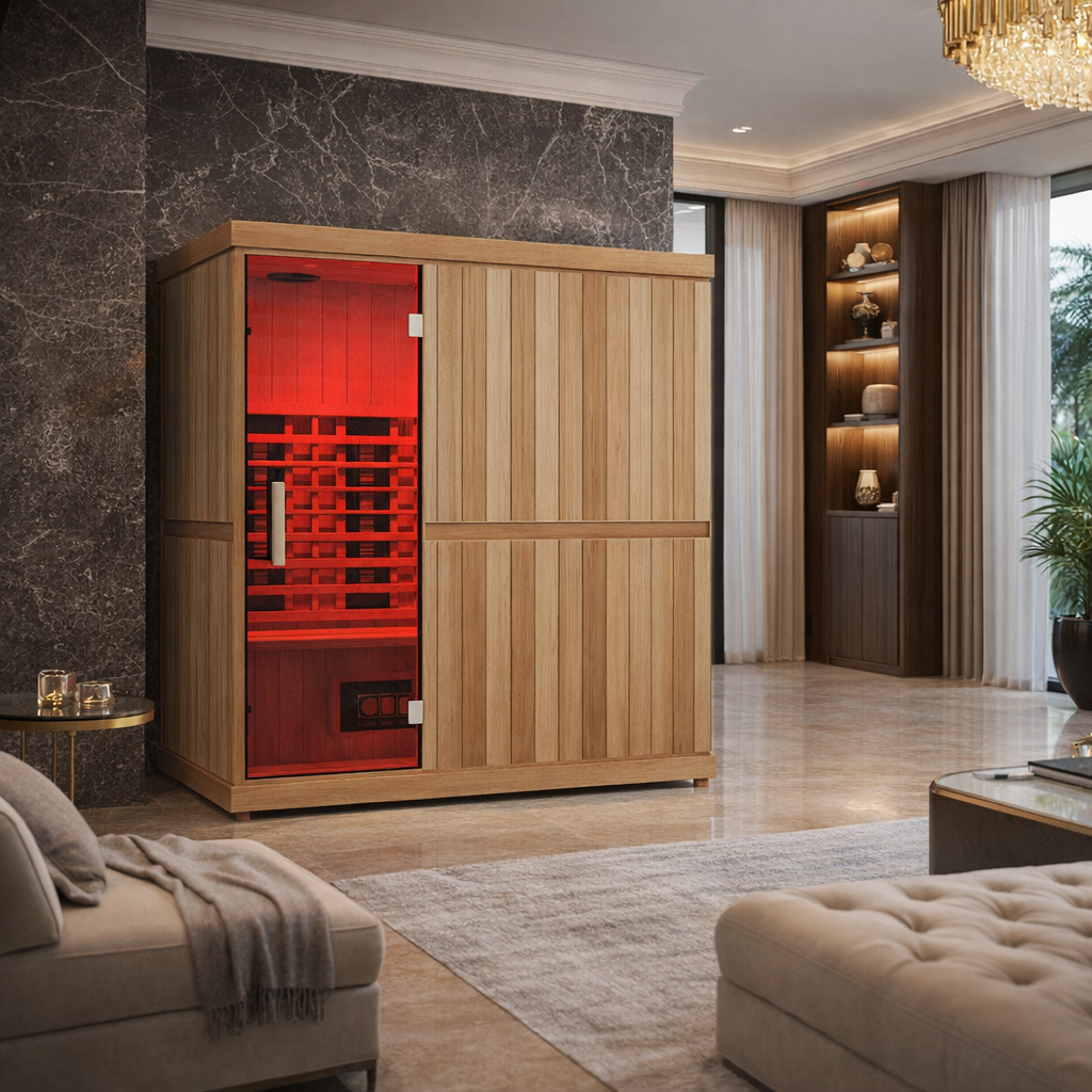
Good sauna ventilation is a design requirement, not a comfort upgrade. Small sauna rooms pack high occupant density, intense heat, significant humidity, and rapidly shifting air conditions into a few hundred cubic feet. Without controlled fresh-air delivery, CO₂ can accumulate quickly, moisture lingers, and the sauna itself—the wood structure, the bench, the ceiling—begins to degrade.
For health context, the broader literature on indoor air quality shows that CO₂ levels above roughly 1,000–1,400 ppm have been associated with measurable reductions in cognitive performance in studies of occupied indoor spaces [NIH/EHP, 2016; EPA]. While direct sauna-specific human studies are limited, the physiological stress of heat makes adequate fresh air even more consequential. Beyond CO₂, PM2.5—fine inhalable particles 2.5 microns or smaller—is linked to cardiovascular and respiratory risk, with WHO and EPA emphasizing that there is no established safe exposure threshold [WHO 2021; EPA PM Pollution].
Moisture is the other axis. Sauna environments generate significant humidity, especially during and after löyly. Damp conditions that are not cleared between sessions provide favorable conditions for mold and microbial growth [CDC Mold Guidance], and persistent moisture accelerates wood degradation. Ventilation that only manages air quality during use—without a post-session drying strategy—is incomplete.
The design goal is not just "air movement." It is controlled dilution, targeted pollutant removal, and a post-use drying protocol, all sized for the specific room volume, occupancy load, and heater type. For an introduction to how this fits within the wider picture of a home wellness space, the home wellness spa design guide covers broader layout and comfort planning alongside these ventilation considerations.
The Short Answer for Designers
Think of sauna ventilation like a dimmer switch, not an on/off button: the goal is controlled fresh-air delivery without sacrificing heat performance.
The core design checklist:
-
Set measurable targets for CO₂, PM2.5, and ACH before sizing any component.
-
Avoid vague "fresh air" language in specs; use ppm, µg/m³, and CFM instead.
-
Commission with instruments after installation.
-
Include a post-session purge strategy in every spec.
Understanding Key Air Quality Metrics: CO₂, PM2.5, and ACH {#metrics}
The three metrics that should drive every sauna ventilation spec are CO₂, PM2.5, and ACH—and they interact. ACH sets the theoretical air turnover. CO₂ tells you whether that turnover is actually diluting occupant-generated pollutants. PM2.5 tells you whether combustion particles are accumulating, especially in wood-fired configurations.
CO₂ Target Range for Small Residential Saunas
CO₂ is a widely used proxy for ventilation adequacy in occupied indoor spaces. As occupants breathe, CO₂ rises; the rate of rise is a function of occupancy load and fresh-air delivery. ASHRAE guidance references approximately 700 ppm above the outdoor CO₂ baseline as a ventilation-related benchmark [ASHRAE 62.1]. In practical terms, this puts a well-ventilated occupied space around 1,100 ppm assuming a typical outdoor baseline of approximately 400–420 ppm.
A practical design target for small residential saunas is to keep occupied CO₂ below ~1,000–1,200 ppm where achievable [EPA; ASHRAE 62.1; NIH/EHP 2016]. This is not a sauna-specific code threshold—it is adapted from general IAQ guidance—and designers should treat it as a planning reference to be verified with measurement, not an assumption baked into the spec.
Key points:
-
Track both baseline and peak CO₂, not single-point readings.
-
Rising CO₂ during occupancy is a signal to increase effective fresh-air delivery, adjust occupancy load, or shorten session length.
-
Consumer NDIR CO₂ sensors typically carry accuracy in the range of ±50 ppm; factor this into your commissioning tolerance [Perplexity dossier; EPA IAQ].
PM2.5 Target Range for Sauna Planning
PM2.5 matters most in wood-fired or combustion-adjacent sauna designs. Combustion generates fine particulates, and a poorly vented or draft-impaired wood stove can produce significant PM2.5 spikes within the room. WHO's PM2.5 guidelines set annual limits at 5 µg/m³ and a 24-hour limit at 15 µg/m³ [WHO 2021]. For short-session residential use, 15 µg/m³ is a reasonable conservative short-term planning reference—not a sauna-specific rule, but a recognized public-health threshold.
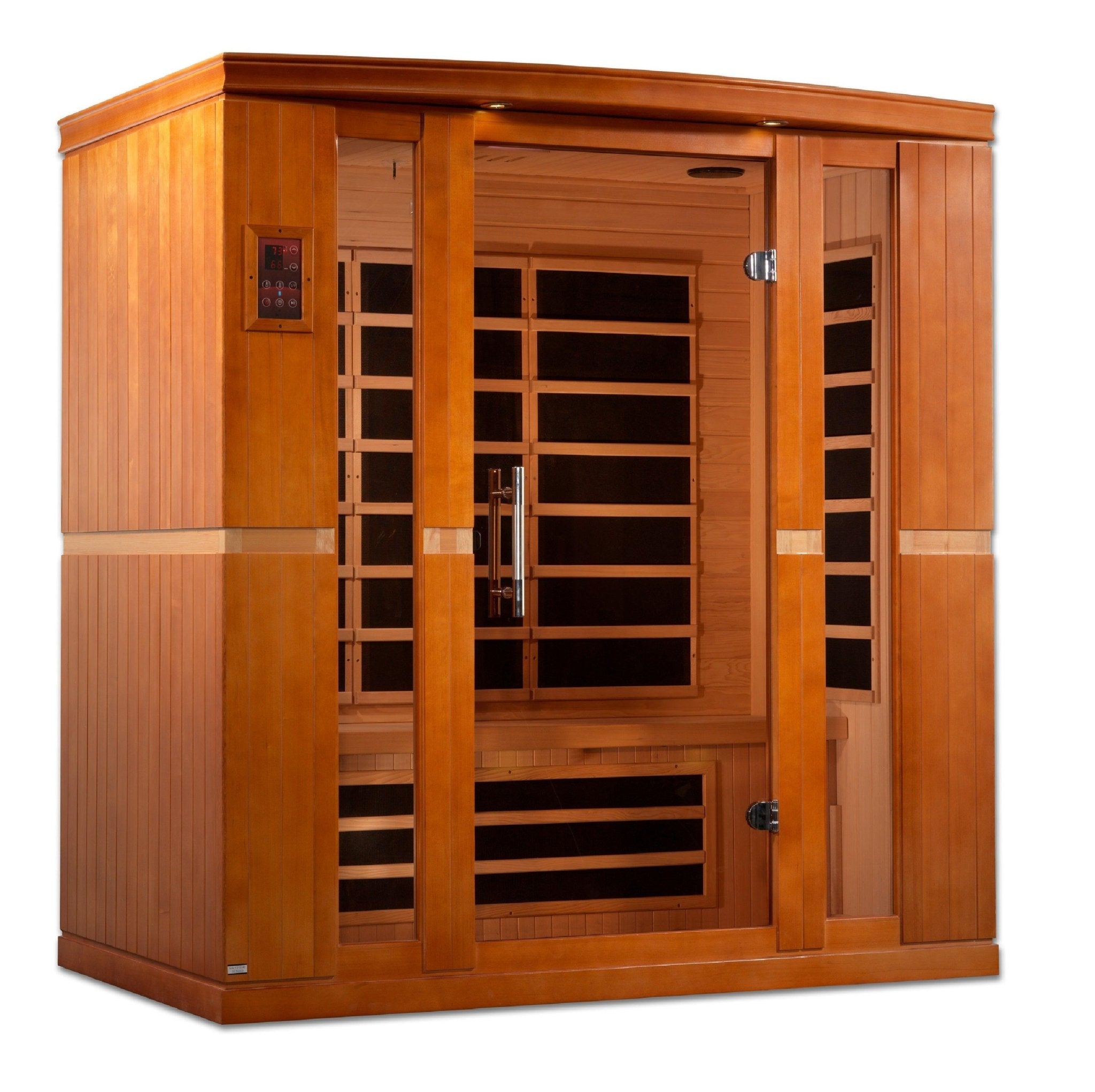
For electric saunas, PM2.5 is generally a lower concern unless there are external combustion sources nearby. For wood-fired saunas:
-
Measure PM2.5 during use, not just in the room at rest.
-
Monitor after stoking and during peak burn.
-
Ensure combustion air and chimney draft meet manufacturer and local code requirements before assessing room PM2.5.
ACH, CFM, and Room Volume
ACH—air changes per hour—measures how many times a room's total air volume is theoretically replaced in one hour [ASHRAE]. It is a planning input, not a guarantee of air quality. A sauna achieving 8 ACH with intake and exhaust on the same wall may perform worse for bather CO₂ exposure than one achieving 5 ACH with a well-designed cross-flow path.
CFM formula:
CFM = room volume (cubic feet) × target ACH ÷ 60
Example: A 160 cu ft sauna targeting 7.5 ACH needs approximately 20 CFM of ventilation capacity.
Use planning tables (see Section 5) rather than isolated rules of thumb. Final CFM targets should account for heater manufacturer guidance, local code requirements, and envelope tightness.
Essential Principles of Sauna Airflow: Natural vs. Mechanical Systems {#airflow-principles}
Airflow strategy determines whether measurable targets can actually be met. The physics of a hot room strongly favor vertical air movement—warm air rises, creating a natural stack effect. Understanding this is the starting point for every layout decision.
Natural Ventilation
In naturally ventilated saunas, airflow is driven by the temperature difference between the hot interior and cooler exterior air, combined with vent placement and available vent area. It is low-cost and mechanically simple.
The limits are significant, though:
-
Performance varies with temperature differential, wind conditions, and building envelope tightness.
-
Airtight modern homes can reduce stack-effect pressure enough to make natural ventilation unreliable.
-
Interior sauna rooms with limited access to exterior walls may not achieve adequate draft without mechanical assist.
Natural ventilation can work well in outbuildings, attached exterior rooms, or designs with direct access to exterior walls and sufficient temperature differentials [ASHRAE Fundamentals; DOE Ventilation].
Mechanical Ventilation
Mechanical exhaust or supply fans provide more stable, predictable airflow—especially valuable in tight residential envelopes, interior sauna rooms, or any design where CO₂ control needs to be verifiable. Mechanical systems reduce variability in ventilation effectiveness [ASHRAE; DOE].
For small residential saunas, a mechanical exhaust fan paired with a passive intake is a common and practical configuration. Key considerations:
-
Specify components rated for high-temperature and high-humidity environments.
-
Avoid PVC ducting near the heater or high-temperature zones (see Section 8).
-
In tight homes, ensure the mechanical sauna exhaust doesn't create negative pressure conflicts with other exhaust systems in the building.
-
Demand-controlled ventilation approaches—where fan speed responds to CO₂ or occupancy signals—can balance air quality with heat performance, though sauna-specific implementations require careful design [NREL Ventilation Research].
Designing for Optimal Air Exchange: Vent Placement, Sizing, and Configuration {#vent-design}
Vent placement determines whether fresh air reaches bathers or short-circuits directly to the exhaust. This is the most commonly under-specified aspect of sauna ventilation design.
Intake Placement
The intake vent introduces fresh, cooler air into the room. Key principles:
-
Place intake near or below the heater level so incoming air mixes with heater-driven convection before reaching bathers; this supports more uniform distribution.
-
Avoid positioning intake directly across from the exhaust vent on the same wall at the same height—this creates a short-circuit path.
-
For electric saunas, intake is typically located near floor level, allowing warm air from the heater to entrain and distribute it upward.
-
Intakes should be adjustable to allow balance during commissioning [LocalMile; North American Sauna Society; ASHRAE Airflow Principles].
Exhaust Placement
The exhaust removes stale, humid, particle-laden air:
-
Place exhaust on the opposite wall from intake, lower than the intake vent, to encourage cross-flow rather than vertical short-circuit.
-
In naturally ventilated saunas, a low exhaust takes advantage of cooler, denser air pooling near the floor.
-
In mechanically exhausted designs, exhaust placement can be more flexible, but avoid configurations that pull air directly across the heater and bather zone without dilution.
-
Mechanical exhaust at a low point helps remove humidity-laden air that settles after a session [ASHRAE; DOE; PMC Ventilation Effectiveness Studies].
Vent Sizing and CFM Calculation
Start with room volume, not guesswork:
-
Calculate room volume in cubic feet (L × W × H).
-
Select target ACH from the planning table in Section 5.
-
Apply: CFM = room volume × ACH ÷ 60.
-
Size vent free area to support target CFM without creating excessive velocity drafts at bather level.
-
Adjust based on occupancy load and measured results after commissioning.
Undersized vents reduce effective ACH even when a correctly sized fan is specified—the vent becomes the restriction [ASHRAE Principles]. Designers should check both the mechanical capacity and the vent free-area capacity.
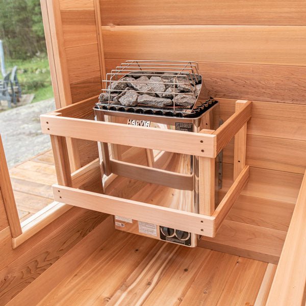
For electric and wood-fired sauna considerations by heater type, our sauna heater buying guide covers heater sizing and configuration differences that affect ventilation planning.
Quantitative Planning Tables: CO₂, PM2.5, and ACH Targets for Residential Saunas {#planning-tables}
The tables below translate IAQ principles and industry guidance into practical design references for small residential saunas. All ACH values are planning estimates—industry-informed and extrapolated from general IAQ principles [LocalMile; North American Sauna Society; ASHRAE extrapolation]—not universal code requirements. Verify with measurement.
Table 1: Room Volume to Target CFM at Three ACH Levels
|
Room Volume (cu ft) |
CFM @ 5 ACH |
CFM @ 7.5 ACH |
CFM @ 10 ACH |
|
120 |
10 |
15 |
20 |
|
160 |
13 |
20 |
27 |
|
200 |
17 |
25 |
33 |
|
240 |
20 |
30 |
40 |
|
300 |
25 |
38 |
50 |
Final CFM targets should incorporate heater manufacturer requirements, local code, occupancy load, and commissioning results.
Table 2: Occupancy Adjustment Reference
Small rooms with higher bather density accumulate CO₂ faster. As occupancy increases, the ventilation system must deliver fresh air more quickly to keep CO₂ below target.
|
Bathers in small sauna |
CO₂ accumulation rate |
Suggested approach |
|
1 |
Low |
Lower end of ACH range (5–6) may suffice; monitor CO₂ |
|
2 |
Moderate |
Mid-range ACH (6–8); monitor peak CO₂ |
|
3–4 |
High |
Upper ACH range (8–10) recommended; consider mechanical assist |
Do not size ventilation based only on heater capacity. Bather load is a primary driver of CO₂ accumulation.
Table 3: Electric vs. Wood-Fired IAQ Priority Comparison
|
Design Factor |
Electric Sauna |
Wood-Fired Sauna |
Design Implication |
|
Primary CO₂ driver |
Occupancy |
Occupancy + combustion context |
Monitor CO₂ during use in both; combustion air must also be accounted for in wood-fired |
|
PM2.5 concern |
Lower (unless external sources) |
Higher due to combustion |
Add PM2.5 monitoring; ensure chimney draft and stove per manufacturer/code requirements |
|
Ventilation predictability |
Better with mechanical assist |
Depends on combustion air, draft, and exhaust design |
Follow manufacturer and local code; mechanical exhaust improves control |
|
Primary commissioning metric |
CO₂ + ACH + comfort |
CO₂ + PM2.5 + ACH + draft performance |
Broader checklist for wood-fired |
|
Post-session purge priority |
Useful |
More important |
Track recovery to baseline |
Evidence confidence: Electric vs. wood PM2.5 distinction is GREEN (EPA; WHO 2021). ACH ranges are YELLOW (industry-informed/extrapolated).
Beyond Airflow: Humidity Control and Temperature Uniformity {#humidity-temp}
Ventilation does more than move air—it manages the moisture and thermal conditions that determine comfort and durability. Two issues warrant specific attention: post-löyly humidity clearance and temperature stratification.
Humidity Control and Post-Session Purge
Steam generated during löyly spikes relative humidity sharply. If that humidity is not cleared between sessions and after use, it can contribute to mold risk and material degradation over time [CDC Mold Guidance]. A post-session purge strategy—keeping vents open or running exhaust for a defined period after the last occupant leaves—is part of complete ventilation design, not an afterthought.
Practical guidance:
-
Specify a post-session vent-open or fan-run period as part of the design (duration depends on room volume and humidity levels; track until humidity normalizes).
-
Measure time to return to baseline CO₂ and humidity as a commissioning step.
-
Include purge-cycle strategy in user documentation for the homeowner.
Temperature Stratification and Air Mixing
In a poorly mixed sauna, significant temperature differences can exist between floor level and head height, potentially exceeding comfortable ranges and creating uneven bather experiences. Good airflow design—with intake and exhaust configured for cross-flow rather than stratified bypass—reduces these gradients [ASHRAE Fundamentals].
Temperature stratification also affects where pollutants concentrate. Stale, humid air tends to pool at low points when ventilation is not actively mixing the room. Measuring temperature at floor, bench, and head height during commissioning gives designers a practical check on mixing effectiveness.
Common Sauna Ventilation Mistakes and How to Avoid Them {#mistakes}
1. Intake and exhaust on the same wall at similar heights. This creates a short-circuit: fresh air enters and exits without sweeping the occupant zone. Result: on-paper ACH is met; bather CO₂ is not controlled. Fix: separate intake and exhaust on opposite walls, or use vertical offset to force cross-flow [ASHRAE; PMC Ventilation Effectiveness Studies].
2. Assuming one vent equals ventilation. A single adjustable vent may serve intake or exhaust but not both simultaneously with controlled airflow. Effective ventilation requires a defined supply path and a defined removal path.
3. No mechanical assist in a tight home. Modern residential construction significantly reduces natural infiltration. A naturally ventilated sauna in a well-sealed home may achieve a fraction of its design ACH. Mechanical exhaust provides measurable, adjustable control [DOE Ventilation].
4. Sizing based on heater, not occupancy. Heater size determines heat output; occupancy determines CO₂ accumulation rate. A 2-person sauna with a well-sized heater can still have poor air quality if ventilation was specified only around heater BTU.
5. Undersized vent free area. Even a correctly sized fan is restricted by undersized vents. Both the mechanical capacity and the vent free area must support the target CFM [ASHRAE Principles].
6. Skipping commissioning measurement. Design and installation assumptions should always be validated. CO₂ and humidity measurements during an occupied session will reveal short-circuiting, inadequate ACH, or occupancy-load mismatches that no drawing can predict.
7. Over-ventilating. More ventilation is not always better. Excessive air change rates reduce heat performance, increase energy use, and can make the sauna uncomfortable. The goal is controlled dilution, not maximum airflow [ASHRAE].
8. Using heat-inappropriate materials. PVC ducting near the heater or high-temperature zones can degrade, off-gas, or fail. Specify heat-rated materials for any components within or adjacent to the hot zone. Confirm with manufacturer guidance and local code requirements.
Advanced Considerations: Materials, Controls, and Troubleshooting {#advanced}
A well-designed sauna ventilation system is commissioned, not just installed. This section covers materials, monitoring tools, and a diagnostic framework.
Measurement and Instrumentation
The minimum instrumentation for commissioning a small residential sauna:
-
NDIR CO₂ sensor: More accurate than electrochemical alternatives; consumer-grade units typically carry ±50 ppm accuracy [Perplexity dossier; EPA IAQ]. Track readings every 5 minutes during an occupied session.
-
PM2.5 monitor: Essential for wood-fired saunas; useful but lower priority for electric systems. Record average and peak readings during and after use.
-
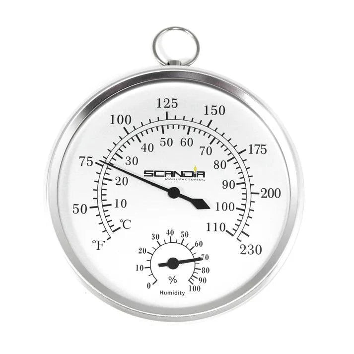
Thermometer/hygrometer: Measure temperature at floor, bench, and head height to check stratification and mixing. A sauna temperature and humidity monitor designed for the sauna environment simplifies this step.
-
Session log: Track date, sauna type, occupancy, session duration, CO₂ start/peak/end, PM2.5 average, and post-session recovery time.
Troubleshooting Matrix
|
Symptom |
Likely cause |
Diagnostic step |
Corrective action |
|
CO₂ rises above 1,200 ppm during use |
Inadequate fresh-air delivery or short-circuit |
Check airflow path; measure intake vs exhaust CO₂ |
Reposition vents; increase fan capacity; reduce occupancy |
|
PM2.5 spike during wood-fired use |
Combustion draft or stove issue |
Check chimney draft; inspect stove door seals |
Address combustion-air supply and flue draft per manufacturer; improve purge ventilation |
|
Persistent humidity after session |
Inadequate post-session purge |
Measure time to return to baseline humidity |
Extend purge cycle; increase exhaust capacity for post-use period |
|
Significant temperature gradient (floor vs head) |
Poor air mixing |
Measure at multiple heights; check vent short-circuit |
Adjust vent placement or add mixing; reconfigure intake/exhaust layout |
|
Comfortable but CO₂ still rises |
Occupancy exceeds design assumption |
Measure CO₂ with actual occupancy load |
Increase ACH or reduce default occupancy assumption in spec |
Demand-Controlled Ventilation
Demand-controlled ventilation (DCV)—where fan speed adjusts in response to CO₂ concentration or occupancy signals—can balance air quality with energy and heat performance in some configurations. Research on DCV in building ventilation shows it can reduce energy use while maintaining IAQ [NREL Ventilation Research]. For saunas, DCV is most relevant in higher-end residential builds where heat retention and CO₂ targets both matter; it requires careful sensor placement and system calibration.
Myths and Misconceptions {#myths}
1. "Saunas don't need ventilation." False. CO₂ accumulates quickly in a small, occupied, airtight room. This myth persists from older, less airtight sauna traditions where natural infiltration provided passive air exchange [EPA; North American Sauna Society].
2. "Heat sterilizes the air." False. Elevated temperature does not remove PM2.5 or reduce CO₂. Particles and gases are not destroyed by heat in normal sauna temperature ranges [WHO 2021; EPA].
3. "More ventilation is always better." Not accurate. Over-ventilation reduces heat performance, increases energy consumption, and can make the room uncomfortable. Controlled dilution is the goal, not maximum airflow [ASHRAE].
4. "CO₂ is harmless in small amounts." Not quite. While CO₂ is naturally present in air, indoor levels around 1,000–1,400 ppm have been associated with reduced cognitive performance in occupied indoor studies [NIH/EHP 2016; PubMed CO₂ cognition study]. In the context of heat stress, adequate fresh air matters.
5. "Wood-burning saunas are more 'natural' and therefore cleaner." Misleading. Combustion is a primary PM2.5 source. Wood-fired saunas require more careful ventilation design for particulate control than electric systems [EPA; WHO 2021].
6. "A single adjustable vent is enough." No. A single vent provides either intake or exhaust but not a controlled airflow path. Effective ventilation requires a defined supply and removal strategy.
7. "ACH is all that matters." Not complete. Ventilation effectiveness—whether fresh air actually reaches bathers and removes pollutants—depends equally on airflow path, vent placement, and mixing. High ACH with short-circuited vents performs poorly at occupant level [ASHRAE; PMC Ventilation Effectiveness Studies].
8. "CO₂ and PM2.5 sensors are unnecessary luxury items." Measurement is the only way to verify that a design performs as specified. Invisible pollutants—CO₂ and fine particles—cannot be assessed by feel alone [EPA].
9. "Humidity replaces the need for ventilation." These address entirely different conditions. Humidity is a byproduct of sauna use; ventilation manages both humidity and air quality. Neither substitutes for the other [CDC Mold Guidance].
10. "All residential saunas need the same ventilation design." False. Heater type, room volume, building envelope tightness, occupancy load, and vent layout all substantially change the design. There is no universal off-the-shelf spec that applies to every small residential sauna.
11. "The 5–10 ACH range is a building code requirement." It is not. This range is an industry-informed planning reference extrapolated from IAQ principles, not a universally codified standard [LocalMile; North American Sauna Society; ASHRAE extrapolation]. Always check local code for applicable requirements.
12. "Post-session ventilation isn't part of the design." It should be. Post-use drying and purge ventilation are part of a complete design. Moisture persistence between sessions is a materials durability and mold-risk issue [CDC Mold Guidance].
Experience Layer: Testing Your Own Sauna Ventilation {#experience}
No one should assume their sauna ventilation is performing well without measuring it. The following is a straightforward approach for designers, builders, or homeowners who want to verify performance at commissioning or during regular use.
Safe Author Test Plan
This protocol is suitable for commissioning a newly installed sauna or diagnosing a suspected ventilation issue. No specialized training is required; consumer-grade instruments are sufficient for planning purposes.
Equipment needed:
-
NDIR CO₂ meter (consumer-grade, ±50 ppm or better accuracy)
-
PM2.5 air quality monitor (for wood-fired sauna; optional for electric)
-
Thermometer/hygrometer suitable for high heat and humidity
-
Notebook or simple phone notes
Protocol:
-
Record room temperature, outdoor temperature, and CO₂ at baseline (empty room, vents in operating position).
-
Enter with a defined occupancy load (1–2 people for a small sauna).
-
Record CO₂ every 5 minutes during a 15–20 minute session.
-
Record PM2.5 average and peak (especially relevant with wood-fired heater).
-
Measure temperature at floor level, bench level, and near head height to assess stratification.
-
At session end, open vents fully or run exhaust; time how long it takes CO₂ and humidity to return to baseline.
What You Might Notice
Results will vary by room volume, occupancy, heater type, and vent configuration. Some common patterns to be aware of—though not guaranteed:
-
CO₂ may rise faster than expected in small rooms with 2+ occupants when ventilation is passive only.
-
Wood-fired saunas may show PM2.5 spikes during stoking that persist for several minutes.
-
Temperature stratification of 15–30°F between floor and ceiling level is common in under-mixed rooms.
-
Recovery to baseline CO₂ after a session may take 10–30 minutes without active post-session exhaust.
Tracking Template
|
Date |
Sauna type |
Occupants |
Session length |
CO₂ start (ppm) |
CO₂ peak (ppm) |
CO₂ end (ppm) |
PM2.5 avg (µg/m³) |
Temp floor / bench / head (°F) |
Recovery time (min) |
Notes |
Run this log at least three times under normal use conditions before drawing conclusions about system performance.
FAQ {#faq}
1. What is a safe CO₂ level in a sauna? A practical planning target is to keep occupied sauna CO₂ below approximately 1,000–1,200 ppm. This is adapted from indoor air quality guidance, not a sauna-specific code threshold [EPA; ASHRAE 62.1; NIH/EHP 2016].
-
CO₂ above this range suggests ventilation is not keeping up with occupancy.
-
Indoor CO₂ around 1,000–1,400 ppm has been associated with reduced cognitive performance in studies of occupied spaces.
-
Outdoor CO₂ baseline (~400–420 ppm) should be factored in; ASHRAE guidance references ~700 ppm above outdoor baseline as a ventilation indicator.
-
Measurement is required—design alone cannot guarantee CO₂ levels.
-
Reduce occupancy or increase fresh-air delivery if peak CO₂ exceeds the target.
2. What ACH is recommended for small residential saunas? Industry guidance and IAQ extrapolation generally suggest 5–10 ACH as a practical planning range [North American Sauna Society; LocalMile; ASHRAE extrapolation].
-
This range is not a universal code requirement; always check local requirements.
-
Higher occupancy and wood-fired systems support the upper end of the range.
-
ACH must be paired with good airflow path; high ACH with short-circuited vents can still result in poor CO₂ control at occupant level.
-
Verify with CO₂ measurement after installation.
-
CFM = room volume × ACH ÷ 60.
3. What PM2.5 level should I design for in a sauna? Use WHO's 24-hour guideline of 15 µg/m³ as a conservative short-term planning reference [WHO 2021].
-
This is a public-health threshold, not a sauna-specific code value.
-
Wood-fired saunas require more active PM2.5 management than electric systems.
-
Measure PM2.5 during use, especially during and after stoking a wood stove.
-
Combustion air and chimney draft issues are the primary causes of elevated indoor PM2.5 in wood-fired configurations.
-
Annual exposure at elevated PM2.5 levels carries cardiovascular and respiratory risk [WHO 2021; EPA].
4. How do I calculate the CFM I need for my sauna? Use: CFM = room volume (cu ft) × target ACH ÷ 60 [ASHRAE].
-
First, measure the sauna interior in cubic feet (length × width × height).
-
Choose a target ACH (5–10 for small residential; use mid-range as a starting point).
-
Divide by 60 to convert from per-hour to per-minute flow.
-
Check that both your mechanical fan capacity and vent free area support the target CFM.
-
Adjust based on occupancy load and commissioning measurements.
5. What is the difference between natural and mechanical sauna ventilation? Natural ventilation relies on the stack effect and temperature differentials to drive airflow; mechanical ventilation uses powered fans for more predictable control [ASHRAE; DOE].
-
Natural ventilation is lower cost and simpler but variable, especially in tight modern homes.
-
Mechanical ventilation provides stable, measurable airflow independent of outdoor conditions.
-
Interior sauna rooms without access to exterior walls generally require mechanical assist.
-
Both approaches require correct vent placement to avoid short-circuiting.
-
The two can be combined: mechanical exhaust with a passive intake is a common residential configuration.
6. Where should I place the intake vent in a sauna? Place the intake near or below heater level to allow incoming air to mix with heater-driven convection before reaching bathers [LocalMile; North American Sauna Society; ASHRAE].
-
Avoid placing intake directly opposite the exhaust at the same height on the same wall.
-
Intake should be adjustable to allow balance during commissioning.
-
Avoid configurations where cold intake air flows directly onto bathers before mixing.
-
Electric and wood-fired layouts may differ based on heater position.
-
Intake free area must support the target CFM.
7. Where should the exhaust vent be placed in a sauna? Place exhaust on the opposite wall from the intake, lower than the intake vent, to support cross-flow and remove humid, stale air from the low zone [ASHRAE; PMC Ventilation Effectiveness Studies].
-
Low exhaust placement helps clear moisture-laden air that settles near the floor.
-
Mechanical exhaust at a low point improves post-session drying.
-
Avoid configurations where exhaust pulls air directly across the heater and bather zone without dilution.
-
In naturally ventilated designs, low exhaust position leverages temperature stratification.
-
Exhaust free area must support the target CFM.
8. Does sauna type (electric vs. wood-fired) change ventilation requirements? Yes, primarily around PM2.5 and combustion air [EPA; WHO 2021].
-
Electric saunas: CO₂ is occupancy-driven; PM2.5 is generally a lower concern.
-
Wood-fired saunas: PM2.5 from combustion requires additional ventilation attention and combustion-air supply.
-
Wood stoves must follow manufacturer requirements and local code for combustion air and flue.
-
ACH range applies to both, but wood-fired systems often benefit from the upper range.
-
Post-session purge is more important for wood-fired systems.
9. What is short-circuit airflow and why does it matter? Short-circuiting occurs when intake and exhaust are positioned so that fresh air exits the room before sweeping the occupant zone [ASHRAE; PMC Ventilation Effectiveness Studies].
-
The result is that measured ACH may meet targets while occupant-level CO₂ remains elevated.
-
It is the most common failure mode in sauna ventilation design.
-
Prevented by placing intake and exhaust on opposite walls and using vertical offset.
-
Commissioning with CO₂ measurement in the occupant zone catches short-circuiting that design drawings cannot predict.
-
Even small adjustments to vent placement can have significant impact on effective ventilation.
10. How does ventilation affect sauna humidity? Ventilation clears steam generated during löyly and helps dry the room between sessions [CDC Mold Guidance; ASHRAE].
-
Post-session exhaust significantly reduces moisture persistence.
-
Inadequate drying between sessions can contribute to mold risk and wood degradation.
-
A post-session purge cycle—running exhaust after the last occupant leaves—should be part of the design spec.
-
Humidity sensors help track recovery to baseline.
-
Humidity management and air quality management are linked but distinct functions of the ventilation system.
11. What is temperature stratification and how does ventilation address it? Temperature stratification is the vertical temperature gradient from floor to ceiling in a sauna; poorly mixed rooms can have large differences between head height and floor level [ASHRAE].
-
Well-designed airflow paths reduce stratification by improving mixing.
-
Measuring temperature at floor, bench, and head height during commissioning reveals stratification issues.
-
Cross-flow ventilation layouts generally produce better mixing than vertical short-circuit layouts.
-
Some stratification is expected and normal in sauna environments; the goal is not elimination but management.
-
Excessive stratification at head height can affect perceived comfort even when air quality targets are met.
12. Are there ASHRAE standards that apply to sauna ventilation? ASHRAE Standard 62.1 provides general ventilation guidance for occupied spaces that forms a useful framework, but there is no dedicated ASHRAE standard specifically for residential saunas [ASHRAE 62.1].
-
The 700 ppm above outdoor CO₂ baseline concept comes from ASHRAE ventilation principles.
-
ACH ranges for saunas are extrapolated from IAQ principles, not codified in ASHRAE for this specific application.
-
Designers should check applicable local building codes for any jurisdiction-specific requirements.
-
ASHRAE Fundamentals provides airflow, stack effect, and ventilation effectiveness principles directly applicable to sauna design.
-
ASHRAE should be treated as a framework reference, not a sauna-specific code.
13. What tools do I need to commission sauna ventilation? A CO₂ meter, PM2.5 monitor (especially for wood-fired systems), and a thermometer/hygrometer are the core instruments [EPA; WHO 2021].
-
NDIR CO₂ sensors are more accurate than electrochemical alternatives; consumer-grade units typically have ±50 ppm accuracy.
-
Measure CO₂ every 5 minutes during an occupied session to track accumulation and peak.
-
A sauna temperature and humidity monitor suitable for high heat and humidity simplifies stratification and moisture tracking.
-
Post-session recovery time (time for CO₂ and humidity to return to baseline) is a key commissioning metric.
-
Total cost for basic commissioning instruments is modest relative to the cost of the sauna.
14. What is the post-session purge and why is it part of the design? A post-session purge is a defined period of active exhaust or open-vent operation after the last occupant leaves, designed to clear humidity and residual pollutants [CDC Mold Guidance; EPA IAQ].
-
Without a purge, moisture and odors accumulate between sessions.
-
Purge cycles are especially important in wood-fired saunas and in rooms without natural air movement.
-
Measure time to return to baseline CO₂ and humidity as part of commissioning.
-
Include purge strategy in the homeowner documentation and operating instructions.
-
A purge cycle of 15–30 minutes of active exhaust is a reasonable starting point; adjust based on measured recovery time.
15. Can I use demand-controlled ventilation in a sauna? Potentially yes, though sauna-specific implementations require careful design [NREL Ventilation Research].
-
DCV adjusts fan speed or vent position in response to CO₂ or occupancy signals.
-
It can help balance air quality targets with heat performance.
-
Sensor placement inside the sauna must account for high heat and humidity conditions; not all consumer sensors are rated for sauna environments.
-
DCV is most practical in higher-end residential builds where both heat retention and air quality are design priorities.
-
Commission with manual measurements before relying on DCV controls alone.
16. How does occupancy affect ventilation design? Occupancy is a primary driver of CO₂ accumulation; designing around heater size alone is insufficient [ASHRAE Ventilation Principles; EPA].
-
Each occupant generates CO₂ at a rate that rises with activity level and heat stress.
-
A room sized for 1 bather performs very differently at 3 bathers even with the same heater.
-
Increase target ACH as occupancy assumption increases.
-
Include bather load in the design specification, not just room volume.
-
Commissioning should be performed at maximum intended occupancy.
17. What materials should be avoided near the sauna heater in ventilation systems? PVC ducting and other heat-inappropriate materials should not be used near the heater or in high-temperature zones [ASHRAE Principles; manufacturer/local code guidance].
-
Specify heat-rated metal ducts and components within the hot zone.
-
Confirm material ratings with manufacturer specifications and local code requirements.
-
Heat-inappropriate materials can degrade, off-gas, or fail under repeated thermal cycling.
-
This applies to duct connectors, grilles, and any hardware within the hot zone.
-
Review all ventilation component specifications for temperature ratings before installation.
18. Is mold a real risk in residential saunas? Yes, especially when ventilation and post-session drying are inadequate [CDC Mold Guidance].
-
Sauna environments generate significant humidity; repeated moisture accumulation without drying creates favorable conditions for mold growth.
-
Good post-session purge ventilation is the primary defense against moisture persistence.
-
Wood materials are particularly susceptible to degradation under repeated wetting and slow drying cycles.
-
Use a humidity monitor to track post-session drying and set a target return-to-baseline time.
-
Mold risk is a durability and health concern; it is part of the design case for complete ventilation, not just a comfort issue.
19. Should individuals with health conditions consult a clinician before sauna use? Yes. People with cardiovascular disease, respiratory conditions, pregnancy, heat intolerance, or relevant medications should consult a physician before sauna use [Mayo Clinic].
-
Heat stress combined with poor air quality can amplify physiological risk.
-
Good ventilation reduces but does not eliminate the need for individual health assessment.
-
High PM2.5 exposure elevates cardiac risk particularly in older adults [WHO 2021; EPA].
-
Design can reduce risk but cannot substitute for individual clinical guidance.
-
Include this note in homeowner documentation and operating instructions.
20. What is the "200 rule" for saunas? The "200 rule" is an informal industry reference suggesting that the total vent area in square inches should roughly equal the sauna volume in cubic feet divided by some factor—formulations vary by source and it is not a standardized code requirement.
-
It is best treated as a rough starting-point check, not a design specification.
-
Proper sizing should be based on target CFM, room volume, and ACH, using the formula: CFM = room volume × ACH ÷ 60.
-
Cross-check against vent free area to ensure the opening can pass the target CFM without excessive velocity.
-
The 200 rule does not account for occupancy load, heater type, or mechanical vs. natural ventilation.
-
Always verify with CO₂ and humidity measurement after installation.
21. What's the difference between ACH and ventilation effectiveness? ACH measures how many times the total air volume is theoretically replaced per hour; ventilation effectiveness measures whether that fresh air actually reaches occupants and removes pollutants [ASHRAE].
-
High ACH with short-circuited airflow can fail at the occupant level.
-
Ventilation effectiveness is influenced by vent placement, mixing patterns, and room geometry.
-
A design achieving 7 ACH with good cross-flow may outperform a design at 10 ACH with short-circuited vents.
-
CO₂ measurement in the occupant zone during use is the practical test of effectiveness.
-
Both metrics matter; neither alone is sufficient.
22. How long should I run exhaust after a sauna session? A post-session exhaust or open-vent period of 15–30 minutes is a reasonable starting estimate; the actual target is the time required to return CO₂ and humidity to baseline [CDC Mold Guidance; EPA IAQ].
-
Measure recovery time during commissioning under realistic conditions.
-
Larger rooms, more occupants, and wood-fired sessions may require longer purge times.
-
A mechanical exhaust that runs automatically on a timer after each session simplifies compliance.
-
Include this specification in the homeowner operating instructions.
-
Track purge time periodically to catch degradation in ventilation performance over time.
Sources {#sources}
-
EPA. Carbon Dioxide (CO₂) and Indoor Air Quality. U.S. Environmental Protection Agency, updated 2024. https://www.epa.gov/indoor-air-quality-iaq/carbon-dioxide
-
EPA. Particulate Matter (PM) Pollution. U.S. Environmental Protection Agency, updated 2024. https://www.epa.gov/pm-pollution
-
EPA. Introduction to Indoor Air Quality. U.S. Environmental Protection Agency. https://www.epa.gov/indoor-air-quality-iaq
-
WHO. WHO Global Air Quality Guidelines. World Health Organization, 2021. https://www.who.int/publications/i/item/9789240034228
-
ASHRAE. Standard 62.1: Ventilation and Acceptable Indoor Air Quality. American Society of Heating, Refrigerating and Air-Conditioning Engineers. https://www.ashrae.org/file%20library/technical%20resources/bookstore/standards-62-1-2019.pdf
-
NIH/EHP. Associations of Cognitive Function Scores with Carbon Dioxide, Ventilation, and Volatile Organic Compound Exposures in Office Workers. Environmental Health Perspectives, 2016. https://ehp.niehs.nih.gov/doi/10.1289/ehp.1510037
-
PubMed. CO₂ and cognitive performance study. National Library of Medicine. https://pubmed.ncbi.nlm.nih.gov/28408590/
-
CDC. Mold — Frequently Asked Questions. Centers for Disease Control and Prevention. https://www.cdc.gov/mold/faqs.htm
-
DOE. Ventilation. U.S. Department of Energy. https://www.energy.gov/eere/buildings/articles/ventilation
-
NREL. Demand-Controlled Ventilation Research. National Renewable Energy Laboratory. https://www.nrel.gov/docs/fy11osti/49593.pdf
-
PMC. Ventilation Effectiveness Studies. National Library of Medicine. https://www.ncbi.nlm.nih.gov/pmc/articles/PMC7115766/
-
North American Sauna Society. Sauna Air Quality. https://www.saunasociety.org/blog/2021/2/2/sauna-air-quality
-
LocalMile. Proper Ventilation for Electrically Heated Sauna Part I. https://localmile.org/proper-ventilation-for-electrically-heated-sauna-part-i/
-
Mayo Clinic. Sauna use: What are the health benefits and risks? Mayo Clinic.
What We Still Don't Know {#gaps}
Sauna-specific IAQ research is limited. Most of the quantitative targets used in this guide are extrapolated from general indoor air quality research and public-health guidelines, then layered onto sauna-specific practice. Several important gaps remain:
-
Sauna-specific CO₂ and PM2.5 exposure studies in residential settings are largely absent. The 1,000–1,200 ppm CO₂ target and 15 µg/m³ PM2.5 reference are adapted from broader IAQ frameworks, not derived from sauna-specific controlled trials.
-
The precise ACH range for residential saunas (5–10) is an industry consensus estimate without a robust body of controlled research behind it. It may be appropriate for many configurations, but individual designs can vary significantly.
-
Wood-fired sauna particulate emissions vary substantially by stove design, fuel moisture content, firing technique, and chimney draft. The magnitude of PM2.5 risk in a given installation is difficult to predict without measurement.
-
Long-term cumulative exposure effects of repeated sauna use under varying ventilation conditions are not well characterized in the literature.
-
Demand-controlled ventilation in sauna applications has received minimal direct study. Benefits observed in office and commercial buildings may translate, but the extreme temperature and humidity of sauna environments create implementation challenges not fully addressed in current research.
Designers who want to move beyond planning estimates should commission their installations with instruments and contribute measured data to the broader knowledge base.
Tab 2
View More ArticlesRelated Posts

Hidden Failure Points in DIY Sauna and Steam Projects: The Year 5 Reality Check

Heavenly Heat Sauna Review: Is It the Cleanest, Safest, and Best Infrared Sauna?

HoMedics Premium Steam Sauna Review: Does the 135°F Upgrade Deliver?

The Complete Guide to the Benefits of Cold Plunge and Sauna (Contrast Therapy)

Indoor vs. Outdoor Sauna Guide: The Ultimate Comparison

Wood Species in Wet Heat: Durability, Off-Gassing & Maintenance Over 10 Years
